The Power Box
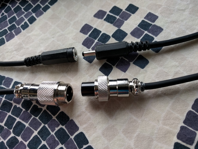
The Power Box came into being after a number of problems occurred. First, there was the issue that all my external components used the same power plug - a 5.5x2.1 barrel connector - but they didn't all use the same voltage. Most were 5V, some were 9V and some were 12V. Mixing them up will at best result a not-working situation, at worst the magic smoke emits. The solution was to either ensure that each voltage had its own, incompatible connector so mistakes could not be made, or to standardize on 1 voltage for everything. Given that multiple voltages also meant multiple power units, and reducing the bulk of the rig is an important factor, I went with having all external components be 5V. It also allowed me to just bring a stack of 5V power units so I would have spares if I needed them. Next came the issue of needing to find a power source where I needed it. Particularly for the camera this became problematic because it was often placed somewhere in the room where there wouldn't be a power source in the direct vacinity. That meant bringing a long power cable and distribution box on the end. That and the power units were, again, bulk that I'd prefer to get rid of. The proverbial straw that broke the camel's back came when someone needed to charge their phone, and decided to just unplug this power cable, which went unnoticed for a while because the camera had an internal battery and nobody checks the HDMI to SDI converter box to see if it's still powered on. When it's plugged in, that's simply assumed. Clearly a change was needed here.
Since all these external components didn't require a lot of power - the typical power unit was rated for 1 amp, so max 5W per component - I decided to try and feed the devices power straight from the main PC's PSU. The PSU can deliver 5V at considerable amperage. More than 10A was nothing special. So I constructed a 10m cable and connected a converter to the PSU. Power light came on, so that worked. Then I connected a source to make the converter work and it instantly went off. The problem was that as soon as the converter actually had to do something, its power draw increased. The formula for voltage drop is Vdrop = IR where I is the amps and R is the resistance of the cable - the thinner the cable to higher the resistance and my cable wasn't particularly thick. By increasing I when making the device do something the voltage drop increased and the device quickly found itself underpowered.
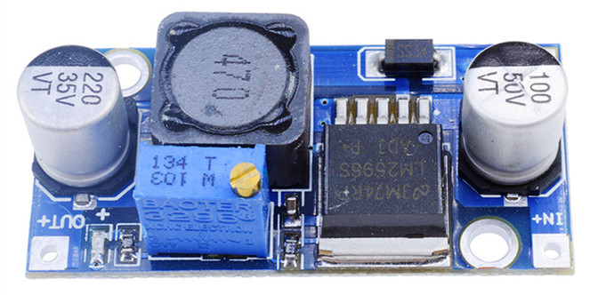
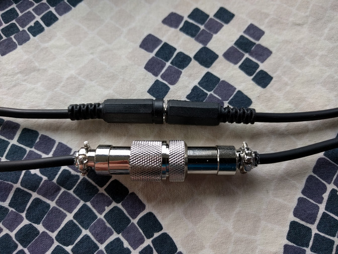
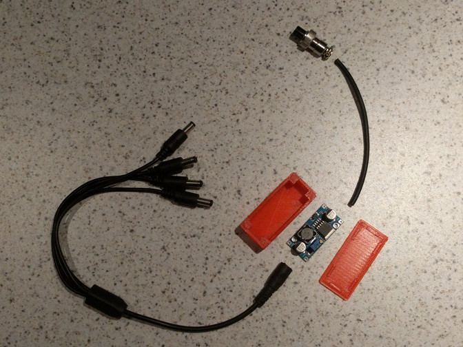
So I went with the 12V line and a DC-DC converter on the far end of the cable to convert whatever's left of the provided power to 5V. Going with 12V had the benefit of lowering the amps that would need to be sent over the line, meaning less voltage drop over distance, and the DC-DC converters you can get for next to nothing on AliExpress were cable of dealing with FAR higher voltages. Since I had multiple components I connected a 1-to-4 barrel splitter to the output connector. One important thing to note is that you should measure the output voltage and adjust it until it provides 5V. In my experience these things, new, are set to dish out what you put into them, which will damage your components. Get a cheap multimeter and set them to anywhere between 5 and 5.25V to ensure they can cope with any power drop resulting from the power drain of all the connected components.
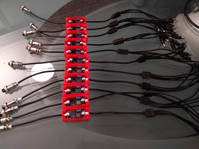
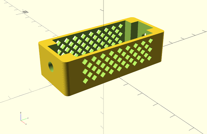
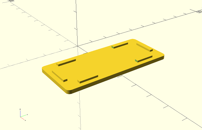
My OpenSCAD file for a box with rounded corners and the OpenSCAD file for the vented power box and its lid. To use, simply place both files in the same directory, then open the second one with OpenSCAD. I tried commenting it a bit but I'll admit the computations aren't particularly neat.